EF Johnson Viking 500 #2 - RT's Radio Home Page
Main menu:
-
 Home Page
-
Amateur Radio
- Caution: READ THIS FIRST!
- Bitten By the Radio Bug
- Station
- Vintage Transmitters
- Vintage Receivers
- Field Day
- Micellaneous Tube Projects
- E.F. Johnson Restoration
- Test Equipment
- British Iron
- Contact
- Food
EF Johnson Viking 500 #2
Amateur Radio > Vintage Transmitters
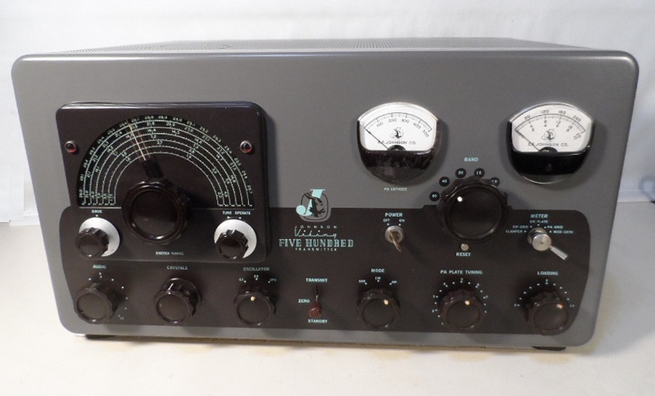
The latest project is yet another Viking Five Hundred. This unit was a real challenge because no power supply/modulator unit came with it. The consensus regarding why there are so many orphaned RF units around is due to families of amateur operators who have passed on have no clue that the big, heavy box on the floor is a neccesary component related to the transmitter unit on the desk. (Credit: Rodger, WQ9E). The units become separated, and the power supply will go a different direction than the RF deck.
This unit is Viking Five Hundred #2 of 2.
New power supply constructed: https://rtsradio.net/500--2-power-supply-project.html
This Viking Five Hundred had been restored on the exterior and was nicely done; in contrast however, it was an electrical challenge on the interior. Strange modifications, circuits removed and others added. The first find was a hard-wired short on the 120 volt line; four damaged switches, and the VFO board had burned due to failure of the 18K "Chernobyl" resistor.
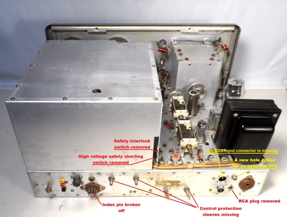
Rear view of the transmitter as found. It makes no sense why someone would remove an existing RCA jack then drill a hole for a new RCA jack right above where the other one was removed.
Metering:
The panel meters:
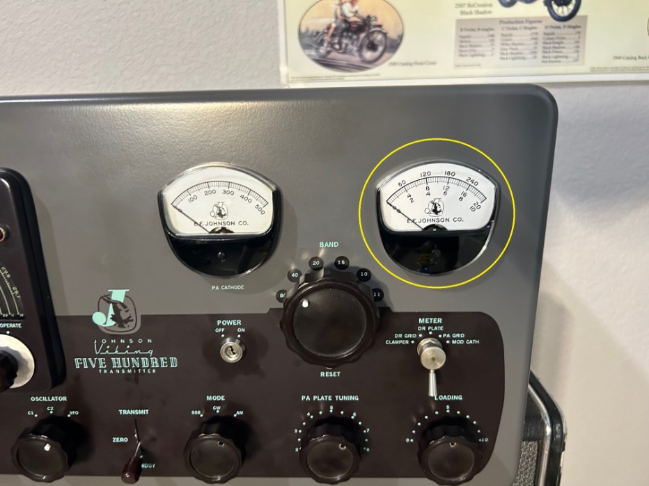
The meters supplied to EF Johnson were produced by "Marion". A nearly identical unit is sold under the "Honeywell" brand, but few parts are interchangeable. Initially, the meters seemed OK, though the Cathode Current meter (left) suffered from maroon paint peeling on its interior.
Multi-meter: Once the RF unit was ready for testing, the multi-meter (right) was sluggish in movement and was sticking in position. Close examination revealed the meter face was a photocopy on cheap paper, and fibers of the paper were obstructing the needle. The paper was also yellowing, so it had to be replaced. Inspecting and testing the meter, it is made by Honeywell and is electrically incompatible with the Viking 500. Fortunately, I have a Viking Valiant parts rig, and the Valiant meter tested identically to the good multi-meter in Viking 500 #1 except the face was the wrong scale.
Disassembling and removing the original meter face from Viking 500 #1, the local Fedex/Office staff made copies of that meter face on premium cardstock. Cutting out the new meter face was straightforward; however, without an accurately sized hole punch, creating the alignment holes in the new face to accept the locating dowels on the meter body proved difficult. The solution was creating the holes by carefully burning them out using a long-tapered soldering tip. 3M #77 spray adhesive was used to attach the new face to the metal face backing plate.
The bezels of the meters were originally colored in the standard Johnson maroon. The Cathode Current meter bezel had been repainted to match the Johnson maroon; this paint was flaking off the inside of the meter. The only matching bezels I had on hand were black Honeywell bezels; these do fit Johnson (Marion) meters, so they were installed.
500 mA Cathode Current meter:
Once the transmitter was in operation, it became clear this meter was reading incorrectly. It was reading about 30% low. Given the readings, this is likely a meter from a Viking Thunderbolt amplifier meter refaced with a 500 mA scale. A 100 mA Marion meter was found on the 'bay", and an external shunt was added. It now reads 500 mA at full scale and is spot-on with a known accurate 500 mA Tripplett meter.
After opening and swapping parts for Various Johnson meters, I suspect they all have the same rated movements. F.S.=5 mA? So far, the meters found in the higher powered gear are internally shunted. Meters for the Valiant and Ranger are all externally shunted at the circuits they serve.
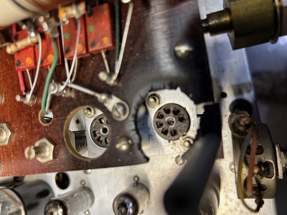
VFO Burnt by Chernobyl Resistor
The VFO had suffered from the degredation and failure of the infamous 18K resistor. In this case, the resistor must have shorted during the meltdown causing the 0A2 regulator tube to overheat and literally burn the phenolic VFO platform.
In Viking Ranger and Valiant transmitters, it would have been easy to replace the entire VFO unit from a donor transmitter; however, the Viking 500 is slightly different as its VFO tuning capacitor shaft also provides the mechanical drive for the auto-tuned RF stages. Ranger and Valiant VFO's lack this drive system.
The best solution was to replace only the phenolic board complete with the the VFO coil and alignment variable capacitors; this donor board came from a Viking Valiant parts rig. The 0A2 socket was also replaced due to damage by the overheating of the 0A2 tube. It was a labor-intensive undertaking, and the outcome was worth the effort. At this point, the 6AU6 was replaced by a 6AH6 as advised by WQ9E; the heater current is higher for the 6AH6 than the 6AU6 which apparently leads to better stability. The repaired VFO works very well, and stability is excellent.
Fast forward to July 2025, using the power supply of Viking Five Hundred #1, the transmitter is alive again and transmitting at full power. Audio was borderline acceptable but is now clean after finding a bad capacitor in the audio circuit. The audio is now excellent.
This Five Hundred had been “re-capped” in the past, and the quality of that particular work is good. Judging from the capacitors used, it was likely done in the 1990’s. Given the age of the electrolytics found in the rig, they were changed out for this build.
November, 2025
Chuck, K1TLI is having a batch of new power supply chassis made, so a deposit was sent. His plan is to have them done before 2026.
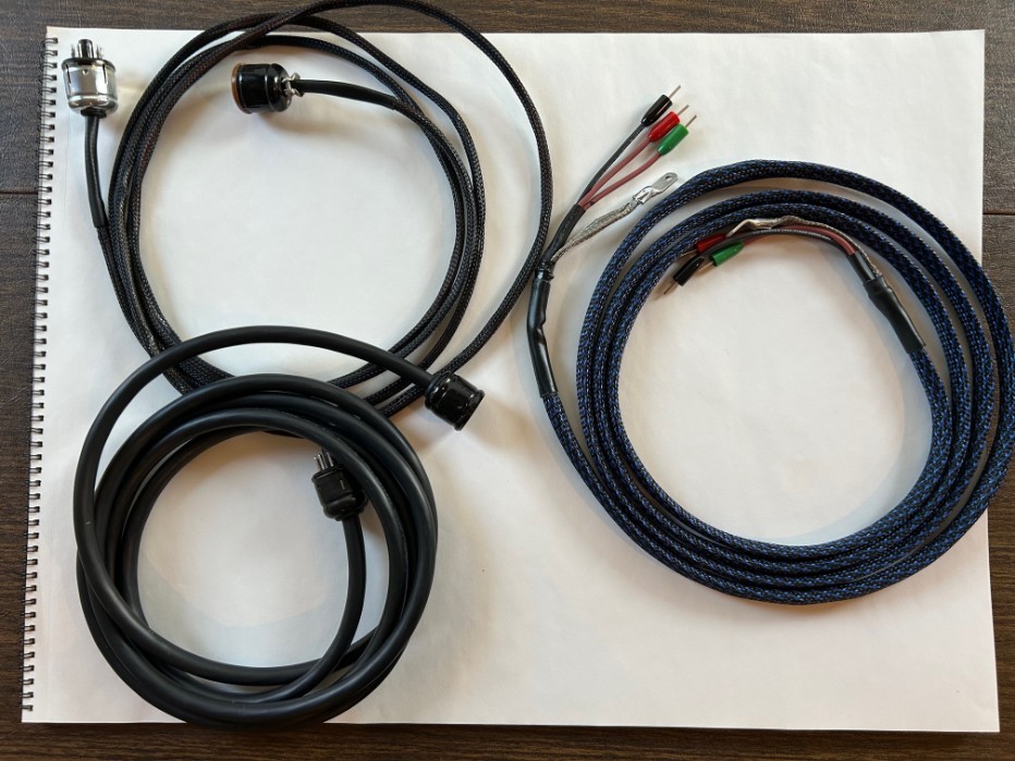
The new umbilical cables: The decision to make 10 foot cables allows more options in locating the power supply unit. The power cord is 15 feet of No.14 AWG.
First on air contact: Using Viking 500 No. 1's power supply/modulator, the first contact/QSO on using this transmitter was with a ham whose opinion I trust. He indicated the audio was excellent.
Tune mode adjustment: Fine tuning the clamper circuit, which controls the screen voltage of the 4-400A final amplifier tube, resulted in the Tune mode is working properly and provides cooler running of the 4-400A in Operate mode.
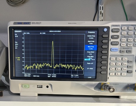
The final test: Conditions were such that the Half Moon Bay KFS SDR was unreachable for the audio test. However, propagation did reach the Northern Utah Web SDR #1. The signal is strong, and the audio sounds good and clear.
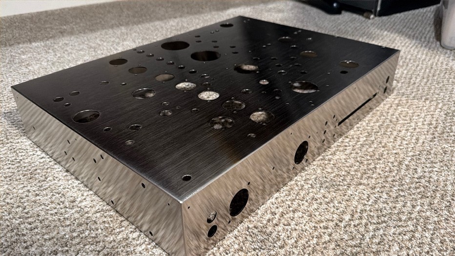
Late December 2025: The new chassis for Viking 500 No. 2's power supply is here! This required a lot of work by K1TLI to re-create this nickel-plated chassis. The power supply project has its own page on this site. https://www.rtsradio.net/500--2-power-supply-project.html
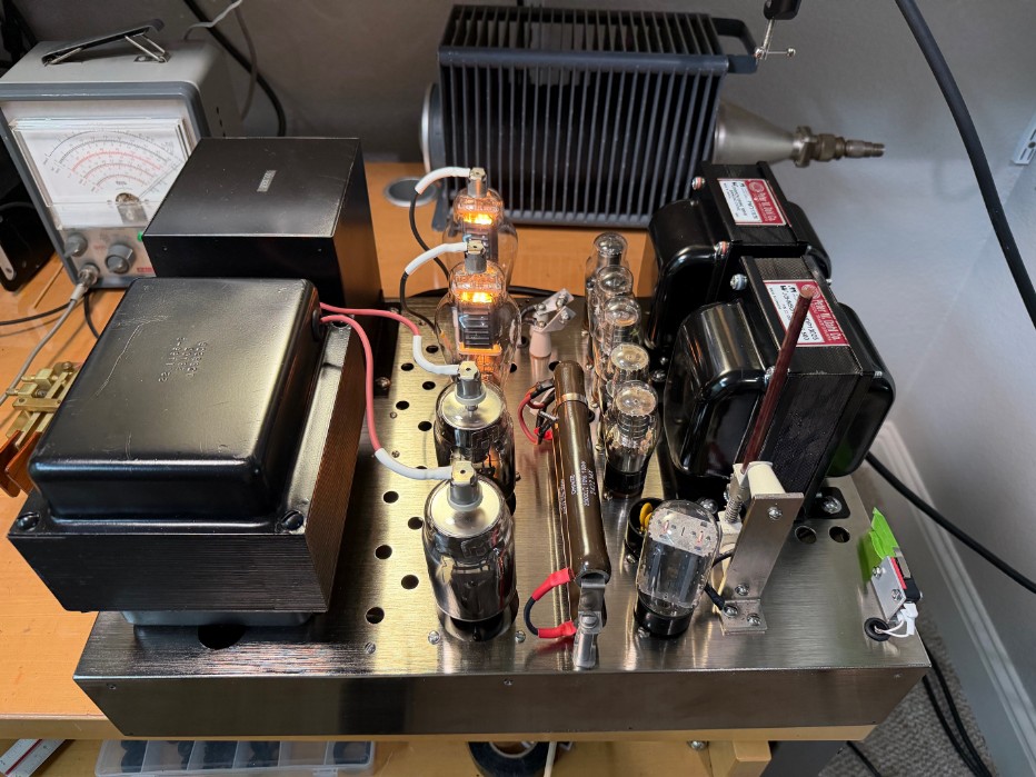
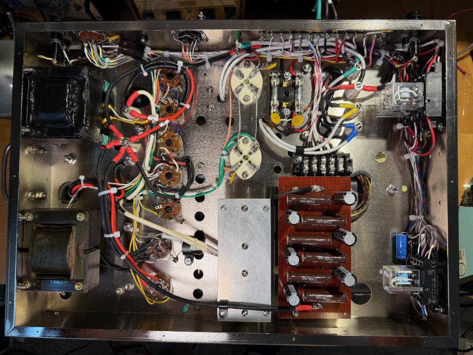
Here is the finished power supply/modulator; it is shown here without its cover installed. It is wired as per the original schematic but with a few added safety and longevity features and variations in some component specifications.
The wiring is complete.
After testing each circuit, full 240 power was applied. The power supply project is a success, and Viking Five Hundred No. 2 produces good power and clean modulation.