The VFO and "Chernobyl" Resistor - RT's Radio Home Page
Main menu:
-
 Home Page
-
Amateur Radio
- Caution: READ THIS FIRST!
- Bitten By the Radio Bug
- Station
- Vintage Transmitters
- Vintage Receivers
- Field Day
- Micellaneous Tube Projects
- E.F. Johnson Restoration
- Test Equipment
- British Iron
- Contact
The VFO and "Chernobyl" Resistor
Amateur Radio > E.F. Johnson Restoration
The Johnson VFO is a good design and is very stable when warm. A few things to be aware of:
1. The Chernobyl resistor: Inside the VFO enclosure, the makers used an 18K, two-watt carbon resistor connected to the plate of the 0A2 regulator tube. Its purpose is to drop the voltage from the 300 volt rail to allow the 0A2 to regulate the VFO B+ to 150 volts.
Time has shown the resistor is not up to the task, and it often fails. It is good practice to replace it at the first opportunity. It is known to fail by increasing in value and subsequently burning up causing damage. Another failure mode is the resistor shorting causing the 0A2 tube to overheat and subsequently burning the phenolic board carrying the VFO components.
The preventive measure is installing a new wirewound resistor. Installing a 20K, five-watt wirewound resistor is a popular repair.
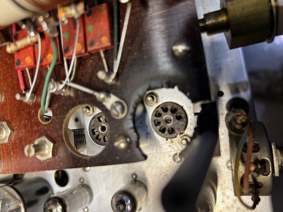
This is a view of the VFO and the phenolic board after the 0A2 regulator tube overheated and seriously burned the board.
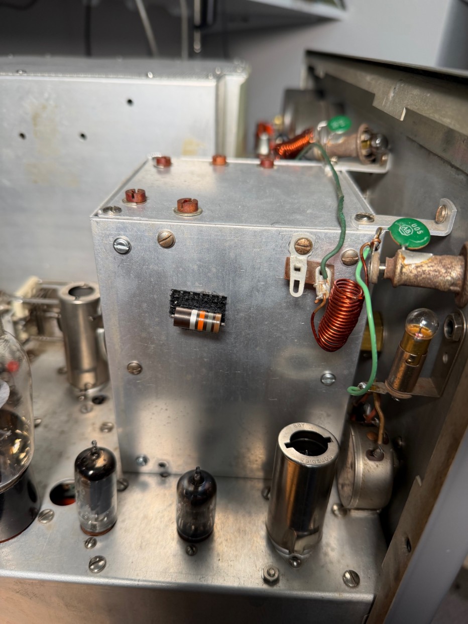
This is the famous 18K Chernobyl resistor. Here is it mounted to a piece of Velcro and applied to the outside of the VFO access door so future technicans know it has been replaced. This is done on all my Johnson transmitters that have VFO's.

Photo showing the Flexible Coupling. The "Chernobyl" resistor had bee previously changed out. If you are this deep into the VFO, it is an opportunity to clean the rotary VFO switch seen in the background.
2. The flexible coupling:
When removing the front panel, care must be taken to avoid damage to the VFO shaft coupling shown in the photo above. This VFO drive coupling is located inside the VFO compartment. It couples the VFO shaft to the Exciter Tuning knob through the ball type reduction drive. This flexible coupling is very susceptible to damage when the front panel of the transmitter is removed. The coupling is attached to the drive shaft by two slotted set screws in the front-most half of the coupling. Loosen, but do not remove the screws as they may be lost inside the VFO compartment.
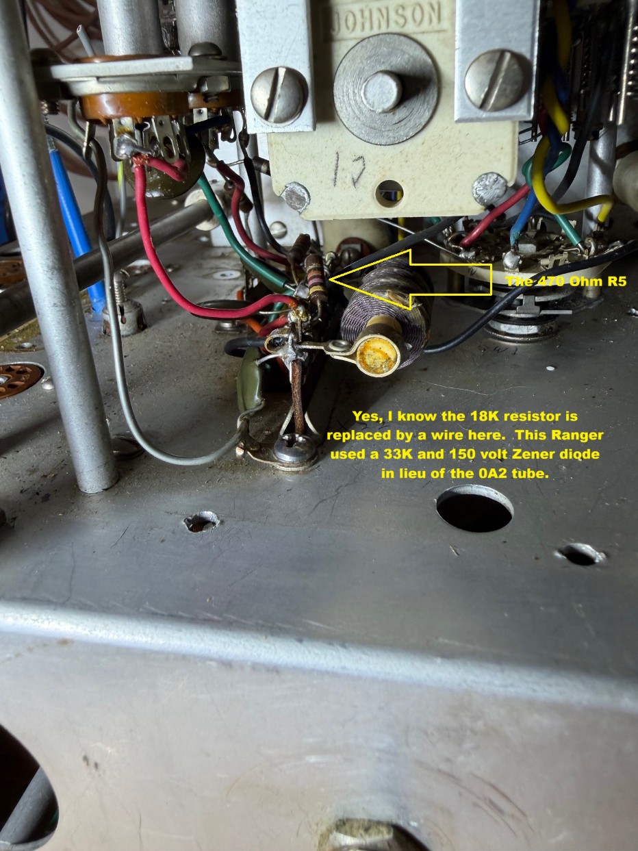
3. The 470 ohm, 1/2 watt resistor (R5 in the Viking Ranger I), inside the VFO had failed by overheating in two of my transmitters. It is located on the terminal strip inside the VFO compartment. Depending on which side of the terminal strip it is found mounted on, it may be possible to replace it through the VFO access side panel; otherwise, the VFO enclosure may have to be removed to gain access. If all seems well during testing except there is no signal from the VFO, R5 may be the issue.