500 #2 Power Supply Project - RT's Radio Home Page
Main menu:
-
 Home Page
-
Amateur Radio
- Caution: READ THIS FIRST!
- Bitten By the Radio Bug
- Station
- Vintage Transmitters
- Vintage Receivers
- Field Day
- Micellaneous Tube Projects
- E.F. Johnson Restoration
- Test Equipment
- British Iron
- Contact
500 #2 Power Supply Project
Amateur Radio > Vintage Transmitters
Background:
The EF Johnson Viking Five Hundred AM/CW transmitter was manufactured as a set of two major components, the Desktop RF Deck and the remote Power Supply/Modulator unit. These two units being connected together by plug-in umbilical cables. The separate units were necessary since power supply itself weighs around 120 pounds, while the RF deck weighs around 65 pounds.
What happened to the original power supplies?
Manufacture of the Viking Five Hundred ended in 1964. AM operation had long been subject to annoying heterodyne interference by other stations on nearby frequencies, so during the 1960's, it was gradually superseded by Single Sideband (SSB) operation. The old heavy, wideband AM transmitters fell out of favor and were often relegated to the garage, other storage area or in sheds. When the owner passes away, the family members are completely unaware that the big, heavy unmarked power supply "box" is a necessary component serving the Viking Five Hundred RF deck, so many of these were sold off separately or sadly, went to the landfill.
The AM transmission mode never disappeared completely from the amateur radio scene. Today, there are dedicated hams who still see value in the AM mode and enjoy operating these classic rigs.
The New Power Supply:
The "Viking 500 #2" RF deck detailed here: https://www.rtsradio.net/ef-johnson-viking-500--2.html was separated from its power supply at some point in history. The RF deck is now operational, so the construction of the new power supply/modulator unit is underway and is detailed here.
A Viking Invader power supply chassis was initially intended as the base for the new power supply; however, extensive modifications would have been required.
A brand new chassis:
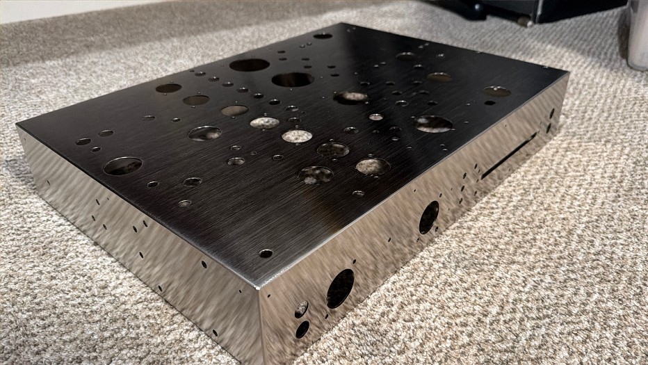
Chuck Hurley, K1TLI reached out to hams who needed a new power supply chassis for orphaned 500 RF Decks. I committed to buy if he could produce them at a reasonable cost. Several other hams committed, and after a few months Chuck came through with a nice product.
The layout must have taken considerable time and effort. The machine work on the chassis is clean, and the nickel plating is well done. The original Johnson chassis was polished to a mirror finish prior to plating; this new chassis was not. Polishing would have likely added significant labor cost to the chassis, so it was best to skip that feature. A few more Viking Five Hundreds may have been saved due to the making of these new chassis; thank you Chuck!
Chuck Hurley does very nice work; here is a link to his website: https://johnsonradioresto.com/home-page
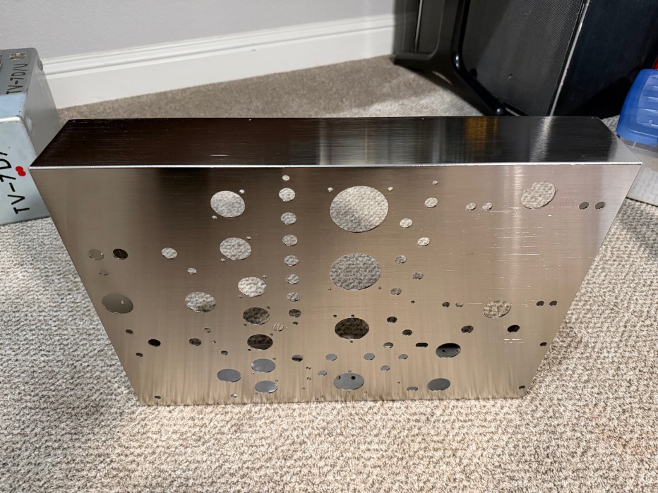
Another view of the new chassis.
I only use good capacitors in my builds. The Viking Five Hundred is a special transmitter, so it deserves higher quality components. The high voltage side of the power supply is fitted with Japanese Rubycon 100uf, 450VDC, 12000 hour radial-leaded electrolytics. These are better than the best axial electrolytic capacitors I found. They were $2.25 each when buying in lots of 10 or more.
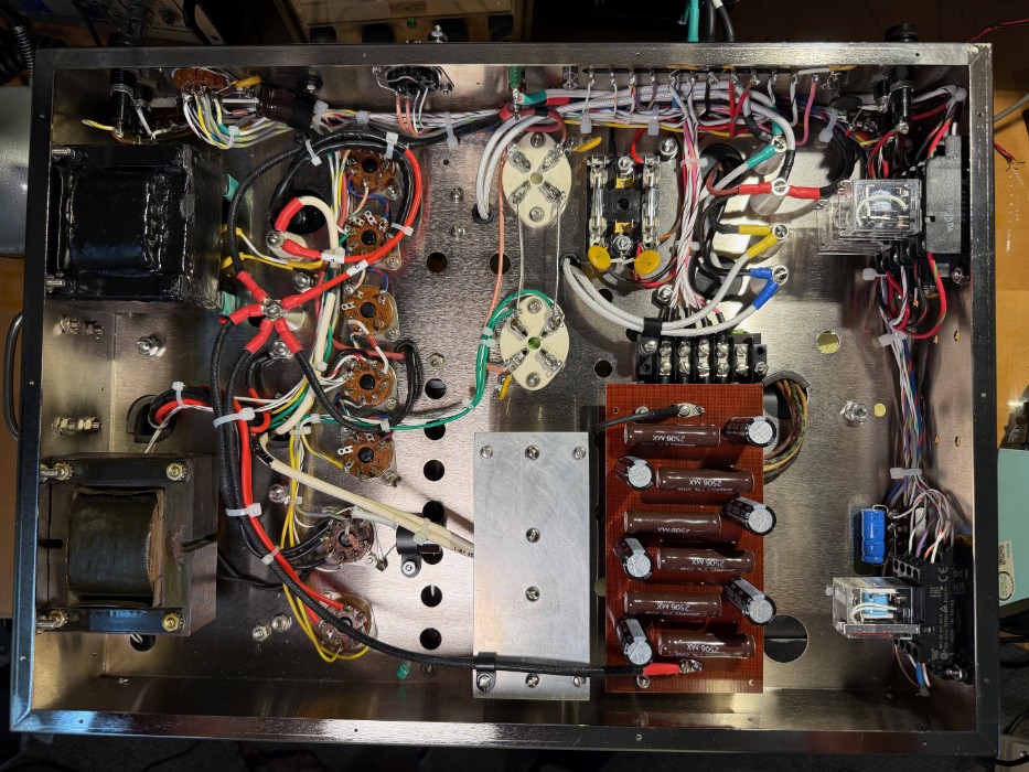
Progress Photo:
The photo shows the major components mounted on the chassis to verify mounting of newer style components, such as relays to verify no conflicts in placement. Wiring has been started; however, a new transformer ordered from Hammond has been delayed for a few weeks. The plan is to have the unit completed and ready for testing in March 2026.
More Progress.
Wiring is about 75% complete. Wire used is #14 AWG Teflon insulated is used for 240 Volt wiring, #18 AWG Teflon is used for most circuits, including some circuits where EFJ used #20. #20 AWG Teflon is used for signal and low-current circuits. Next photo will be after wiring is complete, tied off and tested.
The day of testing:
- Begin with checking out the AC circuits, transformers and chokes with the Ohmmeter. All test well.
- Checking the control circuits. All test well.
- Checking the medium voltage DC circuits (+300DC and -150VDC). Both test well.
- Applying power for the first time using a bypass circuit in lieu of connecting to the RF deck. An external switch and key are used to energize and test for keying. All pass.
- All that is left is to test for acutual operation connected to the RF deck. Will do that during the next session.
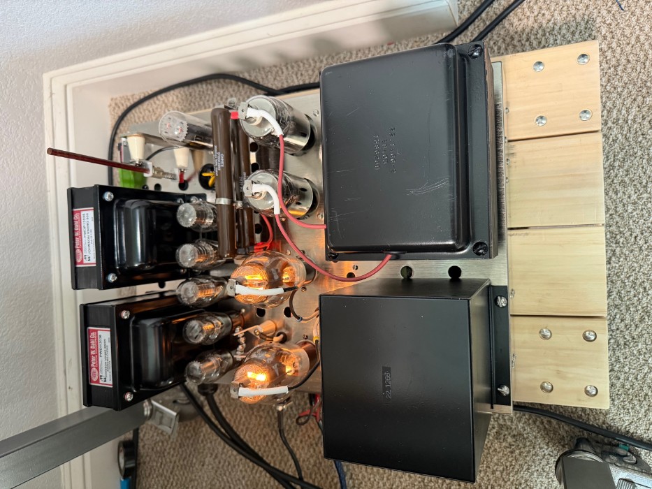
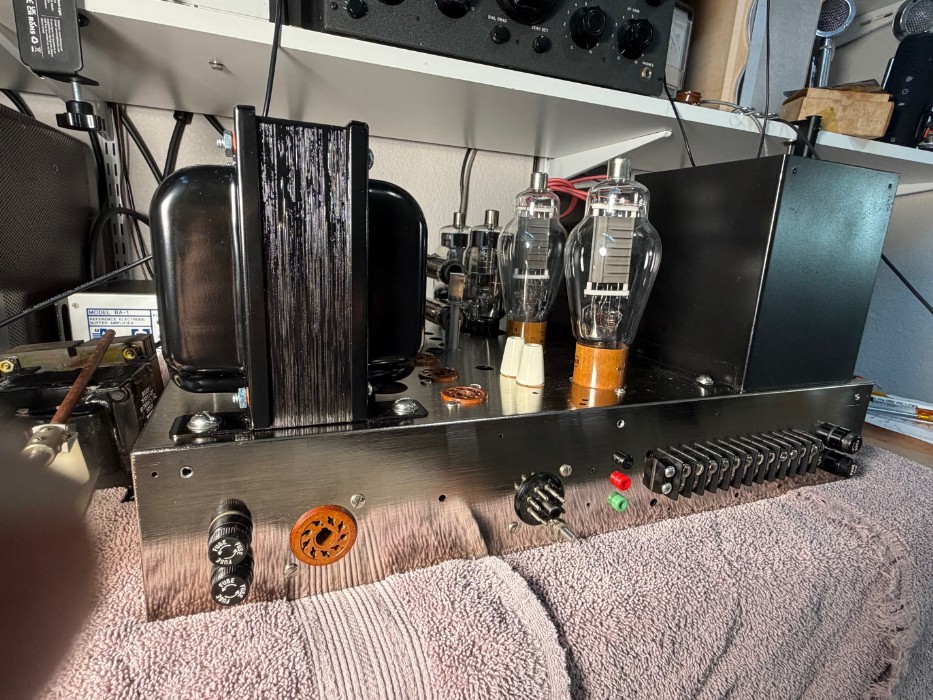
March 24, 2026
It actually works! A few little tweaks here and there then into the case it goes. The plan is to have a dedicated Johnson AM position in the shack. This 500 along with a Ranger II will be the two transmitters. Today is a great day!! :-)
Power Supply Construction:
This power supply/ modulator unit is built on a new production version of the stock, nickel-plated steel chassis. The unit is wired very close to the original schematic, and it should work with any stock Viking Five Hundred RF deck.
The High Voltage transformer and modulation transformer are standard Johnson components for the Viking 500. Availability of components necessitated some changes from the original Johnson wiring layout.
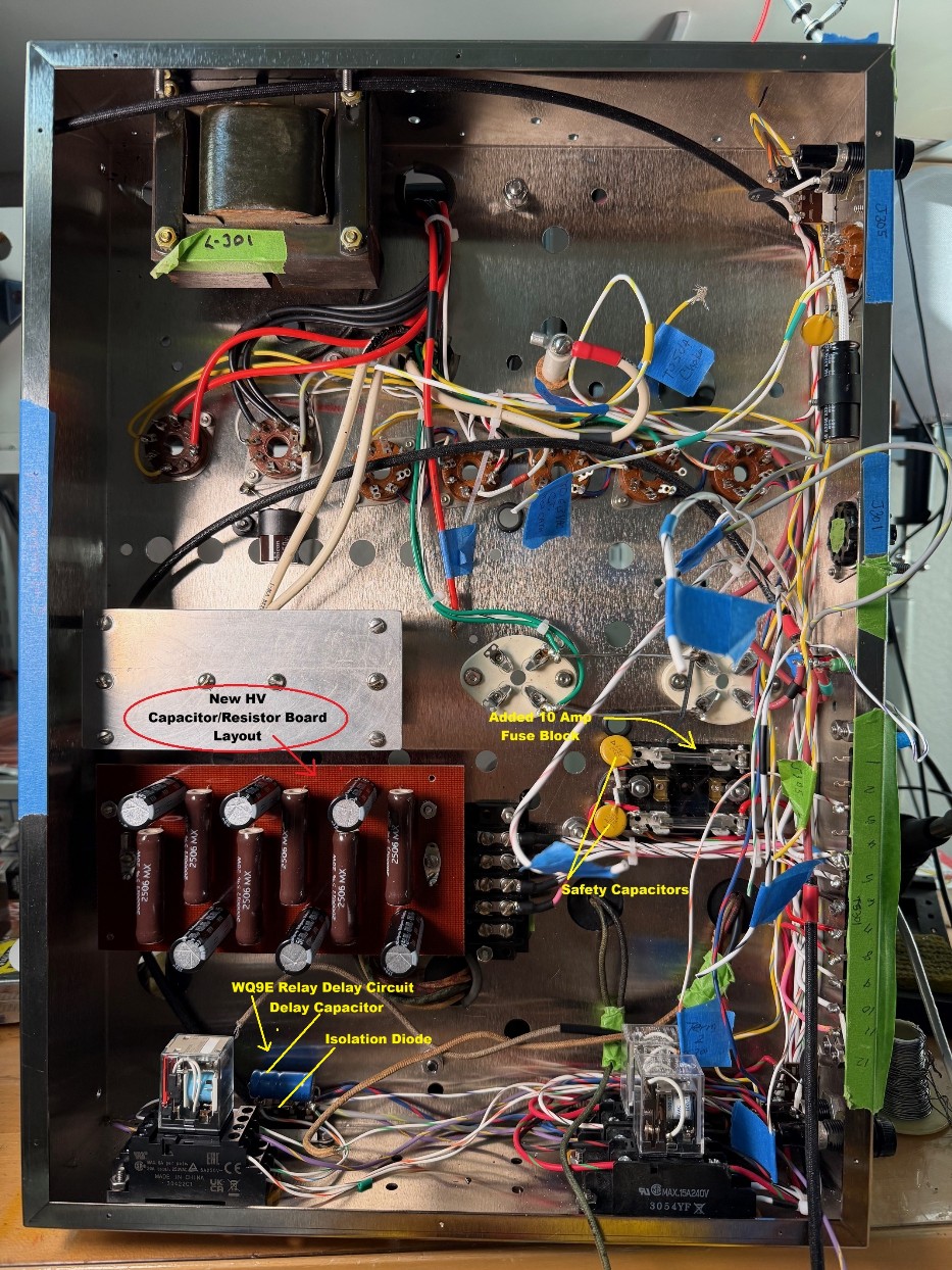
Variances from the original design:
1. The HV choke and medium voltage/ filament transformer are new Peter Dahl (Hammond) standard specification for a Johnson Viking 500.
2. Inrush current limiters are installed on the 120 and 240 volt lines, four total.
3. The upper case and bottom cover come from a Johnson Invader 2000.
4. The HV safety shorting switch is from a Johnson Invader 2000. It is a high-quality component exceeding the specification of the switch used in the stock Viking 500.
5. The safety lockout switch is replaced by a 3A microswitch mounted atop the chassis.
6. A double 10 ampere fuse block was added inside/under the chassis to protect relay RY-301 which was unprotected in the original Viking 500 power supply.
7. New Teflon insulated wire is used in most locations. HV and HV modulator conductors are 18 AWG, 5KV rated rubber insulation.
8. Construction follows the original schematic. However, modern replacement components required mounting changes. Some component specifications vary from the original.
a. The HV power supply now uses high quality, Rubycon long-life, low ESR 100uf 450VDC radial capacitors. The Garolite mounting board is re-configured and lowered to allow vertical mounting of these capacitors.
9. The low and medium voltage chokes vary from original specification.
a. The Low Voltage bias supply (6AX5): Original Johnson manual calls for an 8 Henry component. Installed is a 10-25 Henry swinging choke from a Johnson Invader 2000. The original filter capacitor was 30uf. The new capacitor is 47uf.
b. The Medium Voltage supply (5U4): The Johnson manual specifies a 10 Henry component. Installed is an 8 Henry military specification choke. The original capacitor was 30uf; the new capacitor is 100uf.
10. The octal tube sockets are used items taken from other EF Johnson transmitters. These sockets were chosen because they are an exact fit in the K1TLI chassis.
11. All capacitors and resistors are new components.
12. New NOS GE 3B28 Xenon rectifier tubes are used in lieu of the 866A’s which are thought to be a risk of flashover; this may damage the expensive HV transformer.
13. New old stock GE/RCA 811A modulator tubes are installed.
14. The 5U4 rectifier tube and voltage regulator tubes are used/tested components.
15. 1N4007 rectifier diodes mounted in an octal tube base replace the 6AX5.
16. A 10uf@350VDC electrolytic capacitor and 1N4007 isloation diode was employed to delay unkeying of the 4PDT relay R302. (WQ9E modification.)
Final thoughts:
This power supply/modulator unit was a joy to construct, and it essentially saved a very nice RF deck that had been orphaned at some point in history. From the initial planning stage to completion, the project took about thirteen months. It was an expensive project, but project cost was a secondary concern. If I decide to part with one of the Viking Five Hundreds, it will likely be 500 #1.